Category Archives: Refining Operations

How FCC Feed Hydrotreating Affects FCC Yields And Economics

How FCC Feed Hydrotreating Affects FCC Yields And Economics

The following paragraphs show an example of the effects of hydrotreating ANS VGO on a typical FCC operation.  The focus of the discussion is to compare FCC feed hydrotreating with FCC product treating as competing options for making low sulfur gasoline and diesel fuels.

Table 1 presents the properties of virgin ANS VGO and compares them with the properties of the VGO after severe hydrotreating (95% desulfurization).  Hydrotreating increases the API gravity of the VGO by about 5.5 numbers, increases the aniline point by 10°F, lowers the nitrogen level by about 50% and lowers the VABP by 24°F.  The VABP reduction is the result of a small amount of hydrocracking that occurs in the hydrotreater.

Table 1: Impact Of Hydrotreating on ANS VGO Properties

Table 1

Table 2 summarizes the effects of hydrotreating the feed on the FCC operation.  The FCC unit was air rate limited.  The results show that FCC feed hydrotreating increases conversion by over 10 volume percent while decreasing the yield of dry gas and substantially lowering delta coke. Because of the improvement in delta coke, the riser temperature could be increased and the feed temperature could be decreased slightly without increasing the coke yield or the air rate.  These adjustments helped to increase the gasoline octane (R+M)/2 by 0.65 numbers versus the base case.  The FCC gasoline sulfur was reduced to 20 ppm so that it could be successfully blended directly into a gasoline pool that requires a maximum of 30 ppm sulfur.

TABLE 2: Hydrotreating Effects on FCC Performance with ANS VGO 
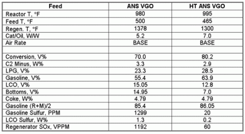
Table 2

Since the LCO sulfur from the hydrotreated feed operation is substantially lower than the base case LCO sulfur, the cost of making ultra low sulfur diesel will be lower.  Also, FCC feed hydrotreating greatly reduces the level of SOx from the FCC regenerator, eliminating the need for the use of SOx reduction agents or the operation of a flue gas scrubber.

With all of the advantages for FCC feed hydrotreating, it might appear obvious that this would be the best choice to make low sulfur products.  However, due to the lower capital cost of product treating, many refiners have chosen this option.  Nevertheless, current economics have made FCC feed hydrotreating more attractive relative to product treating. This is shown in Table 3, which compares a product treating case with FCC feed hydrotreating for ANS VGO.  Using the yields from Table 2, the feed treating case shows a $5.44/bbl advantage in FCC product value. 

TABLE 3: Economics of Hydrotreating ANS VGO
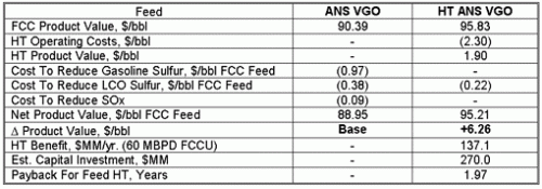
Table 3

BPD moderate pressure FCC feed hydrotreater, would be about $270 MM, leading to a payback period of about 1.97 years.  The conclusion is that, in the long run, refiners will profit from installing FCC feed hydrotreaters.  For refiners who have not already been required to install product treaters and flue gas scrubbers (for SOx reduction), the relative attractiveness of feed hydrotreating is even greater.   For more discussion on these and other related topics, the reader may be interested in the following upcoming technical seminars from Refining Process Services:

Fluid Catalytic Cracking Process Technology   Sept. 17, 18, 19
FCC Unit Troubleshooting     Sept. 20, 21
Hydrotreating & Hydrocracking Process Technology  Oct. 3, 4, 5

These programs (along with 11 others on various refining topics) will be offered at the Crowne Plaza Houston North Greenspoint Hotel. More information is available at www.petroleumrefining.com

Posted By: Robert J. Campagna, Refining Process Services, Inc.

SWS Pumparound Startup

The issue is starting up a Sour Water Stripper (SWS) with a pumparound system.  One concern was the pumparound pump suction going dry before sufficient level was maintained.
 
Summary responses:

On a recent SWS start up, condensate was injected into the pumparound pump suction.  A jumpover also permitted recycling bottoms to feed for warmup prior to startup.
_____________________________________________________________

The pumparound water will become the worst quality water in the system (high NH3 and H2S). Condensate, boiler feed water, stripped water or SWS feed could be used to the suction of the pumparound pump to fill the pumparound section up.  Water with any hardness (service, fire or hard process water) should not be used.
_____________________________________________________________

We filled our 500-gpm SWS via a 2” service water line to the pumparound pump suction. Once there was a high level in the bottom of the tower, we recirculated bottoms-to-feed (with the tower vented to atmosphere) and gradually ramped up the steam to the reboiler.  Once the tower pressure was up to ~ 5 psig we started the pumparound pump, increasing steam as necessary to maintain positive pressure.

Establishing pumparound circulation before the tower is venting steam could be a problem. Usually the chimney tray has weep holes, in which case the pumparound pump may lose suction without supplemental water makeup. A welded chimney tray should be considered as  gaskets tend to wash out in spots, requiring supplemental water injection to the pumparound section.

Consider locating the overhead TI in the top of the tower, rather than in the offgas line, where heat from the steam tracing will give a false high indication in the temporary absence of offgas flow during startup.

A TC bypass around the pumparound cooler allows the operator to maximize the pumparound rate and water temperature and minimize H2S concentration and corrosivity. 

On a recent SWS start up, a jumper from the feed line to the pumparound return line was used to inventory the pumparound system.

Duke Tunnell
for the ABPG
 

TGT SS Quench Column

The issue is the value of a 316 SS quench column and 316 cladding of the quench water coolers with caustic addition on automatic pH control.

Summary comments:

Recent new TGUs have CS quench and absorber shells.  Quench coolers are CS shell and 316 SS tubes, with quench water on the shell side.  Corrosion allowance in the quench tower is 0.25”.
__________________________________________________________________

HIC plate CS with a 0.25″ corrosion allowance for the quench towers, with 304L SS tubes in the quench water cooler.
__________________________________________________________________

Trend seems to be more requests for SS cladding of the quench column (and alloying up in general).  One factor might be reduced cost of cladding due to improved automated fabrication techniques. 

Experience with a 20-year-old unit is that CS is sufficient.  Corrosion may be due to chronic SO2 breakthroughs.  The key to avoiding breakthroughs is reliable H2 measurement. 

Quench column design with the tail gas entering downward at a 45° angle should achieve some initial cooling by impingement on the liquid level, particularly if water recirculation is lost. It should also avoid impingement on the far vessel wall and reduce localized corrosion at the opposite side.  The problem might be greater with packing, where droplets raining down are more prone to being slammed against the wall.
_____________________________________________________________________
 
With a standard SCOT design (i.e., a properly sized reactor, H2 make-up available if indirect preheat, etc), CS should be adequate.  Failure to control SO2 breakthrough into the quench column can result in sulfur deposits on the walls and under-deposit corrosion, including H2 blistering.
_____________________________________________________________________

With caustic addition for pH control, low chloride caustic should be ordered – usually a more costly grade – to avoid chloride cracking of the stainless.

Duke Tunnell
for the ABPG

Hello Refining Online Users!

Another first from Refining Online since it started over 12 years ago! A blog for the refining industry called ROL Blog.

Please review the articles on ROL Blog and feel free to post comments on the subject matter. Comments will be reviewed and posted upon acceptance.